


Oscilloscope
HOT PRODUCTS
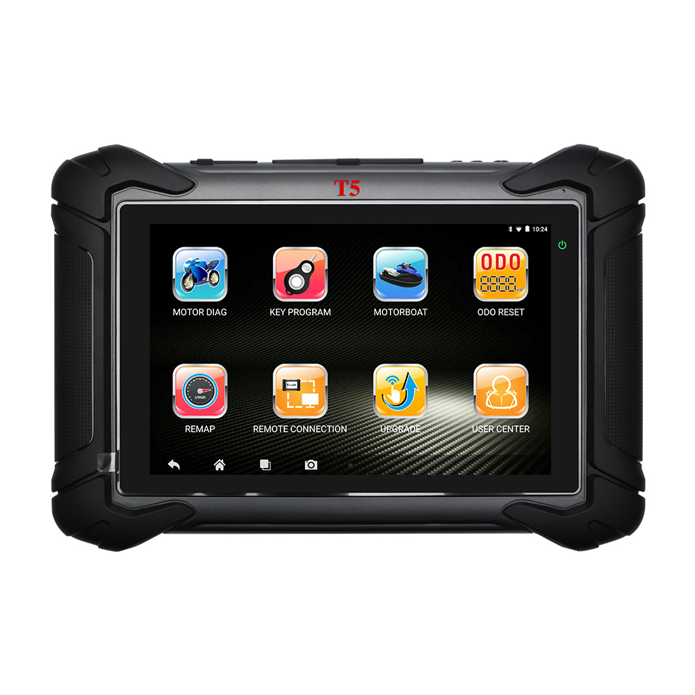
- Heavy-duty Motorcycle Scanner MST T5
- OBDEMOTO MST T5


- DESCRIPTION

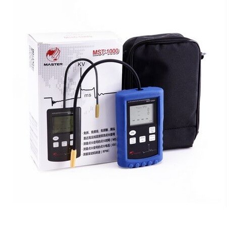
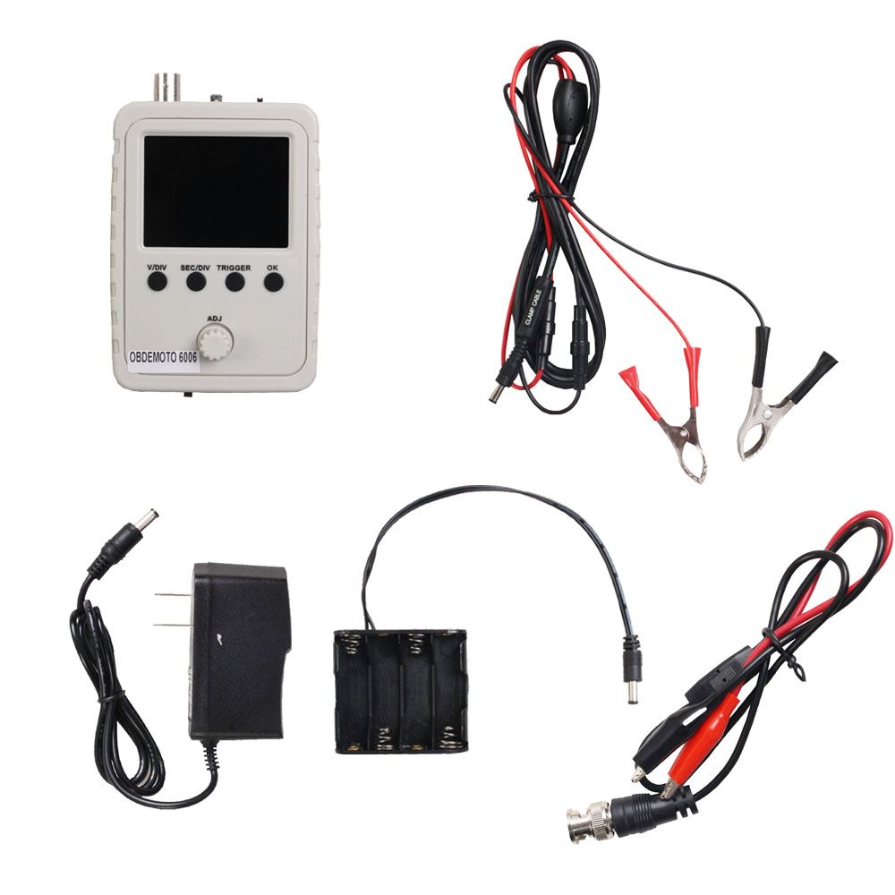
OBDEMOTO-6006 Oscilloscope
Introduction:
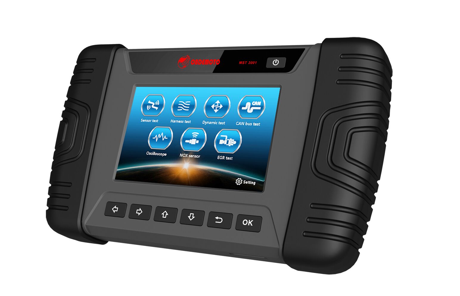
This digital tester is a handheld oscilloscope that specializes in measuring the performance of sensors and actuators for cars/motorcycles. It provides advanced troubleshooting capabilities for service technicians with a simple operator interface.
When testing, the oscilloscope needs to supply power independently, and the power supply voltage is 12V DC. If the voltage is too high, it will damage the instrument. Using a clip probe allows the maximum signal input voltage to be 50Vpk (100Vpp).
Oscilloscope User Manual:
Power on
Power supply: Connect the DC 12V power supply to the power input socket at the bottom (the center conductor is positive), and the voltage of the power supply must be between 9V and 15V.
Probe: Connect the probe to the BNC connector on the top.
Turn the power switch to the ON position. After the power is switched on, the instrument automatically enters the measurement interface after the instrument starts normally
Function button instructions after power on
Coupling switch: the coupling switch can be set to DC (DC signal), AC (AC signal) or GND (ground).
When the switch is placed in the GND position, the input of the oscilloscope is disconnected from the external input and connected to the ground, that is, the input is 0V.
DC or AC signal can be selected according to the type of measurement signal.
Test signal output: this test output is used for production debugging, and this function can be ignored.
BNC connector: connect test clamp, red clamp to signal terminal, black clamp to ground, as shown below.
Parameters instruction of waveform measurement
Although this manual will describe how to connect to the component under test, we strongly recommend that you had better carefully refer to the manufacturer's manual to determine the wire color or PCM wiring harness connector function according to the circuit diagram before any testing and maintenance.
After the waveform is displayed, the waveform can be in the best measurement and diagnosis state through adjusting the button of [ISEC/DIV], and then the relevant parameters of the waveform could be read.
Introduction:
This digital tester is a handheld oscilloscope that specializes in measuring the performance of sensors and actuators for cars/motorcycles. It provides advanced troubleshooting capabilities for service technicians with a simple operator interface.
When testing, the oscilloscope needs to supply power independently, and the power supply voltage is 12V DC. If the voltage is too high, it will damage the instrument. Using a clip probe allows the maximum signal input voltage to be 50Vpk (100Vpp).
Oscilloscope User Manual:
Power on
Power supply: Connect the DC 12V power supply to the power input socket at the bottom (the center conductor is positive), and the voltage of the power supply must be between 9V and 15V.
Probe: Connect the probe to the BNC connector on the top.
Turn the power switch to the ON position. After the power is switched on, the instrument automatically enters the measurement interface after the instrument starts normally
Function button instructions after power on
Coupling switch: the coupling switch can be set to DC (DC signal), AC (AC signal) or GND (ground).
When the switch is placed in the GND position, the input of the oscilloscope is disconnected from the external input and connected to the ground, that is, the input is 0V.
DC or AC signal can be selected according to the type of measurement signal.
Test signal output: this test output is used for production debugging, and this function can be ignored.
BNC connector: connect test clamp, red clamp to signal terminal, black clamp to ground, as shown below.
Parameters instruction of waveform measurement
Although this manual will describe how to connect to the component under test, we strongly recommend that you had better carefully refer to the manufacturer's manual to determine the wire color or PCM wiring harness connector function according to the circuit diagram before any testing and maintenance.
After the waveform is displayed, the waveform can be in the best measurement and diagnosis state through adjusting the button of [ISEC/DIV], and then the relevant parameters of the waveform could be read.