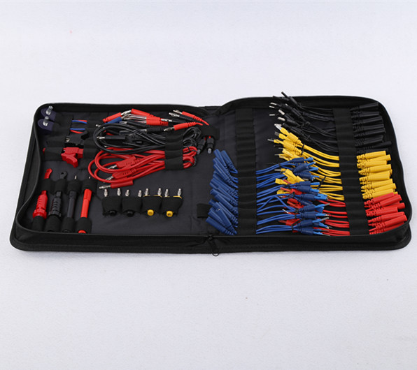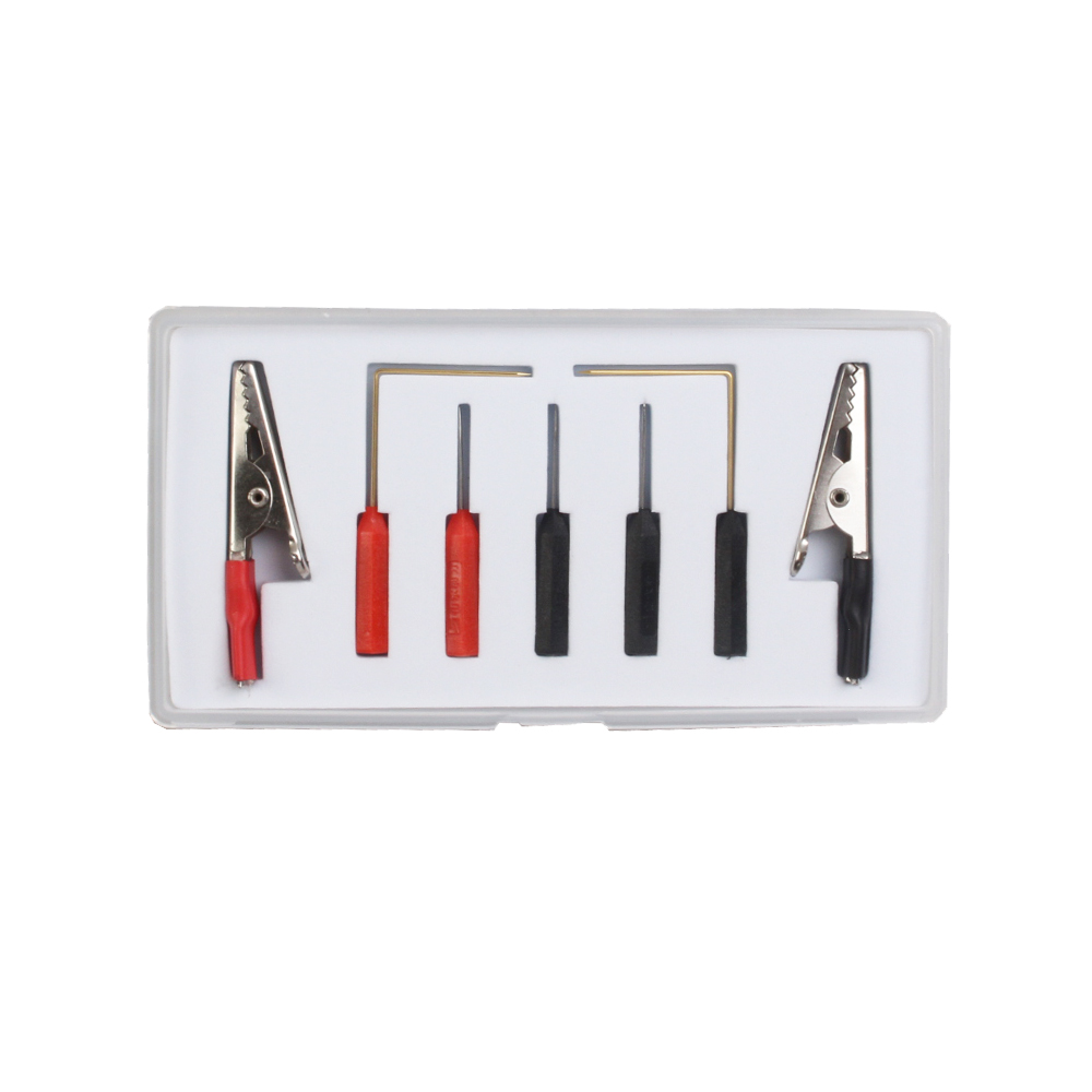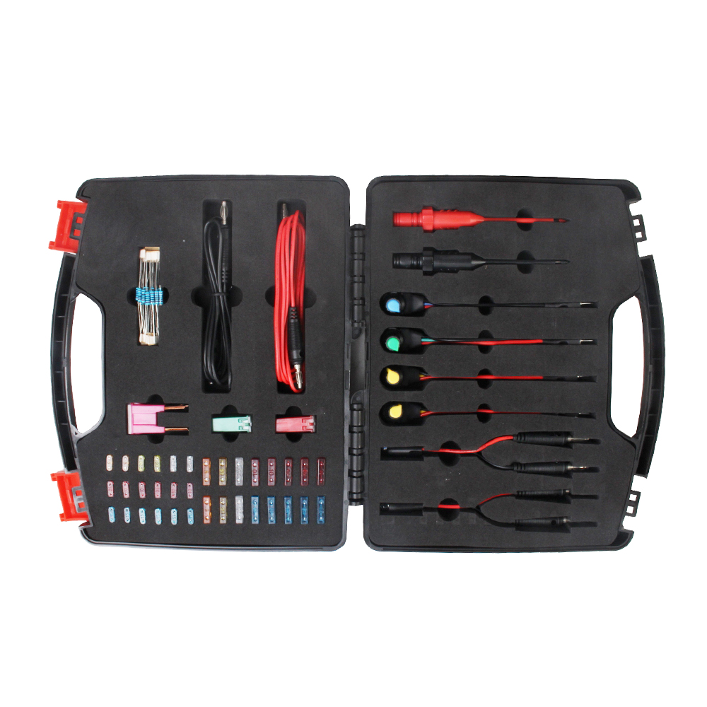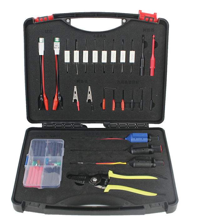


circuit and adapters
HOT PRODUCTS
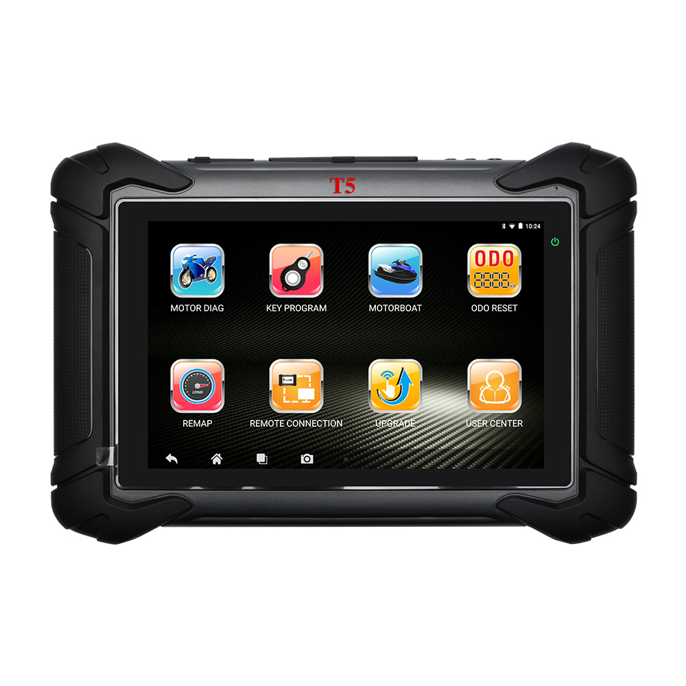
- Heavy-duty Motorcycle Scanner MST T5
- OBDEMOTO MST T5


- DESCRIPTION

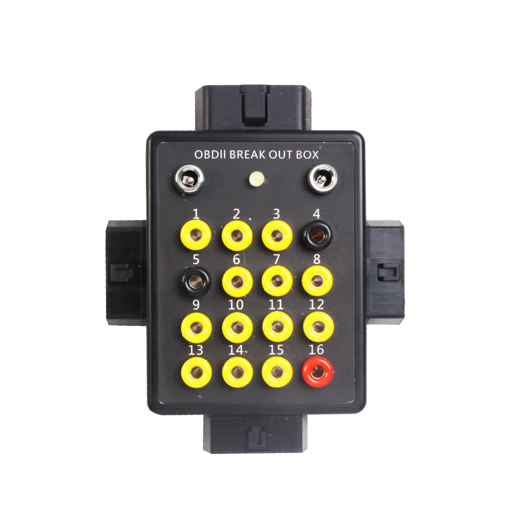
OBDEMOTO 6010 OBDII Signal Conversion Box Instructions
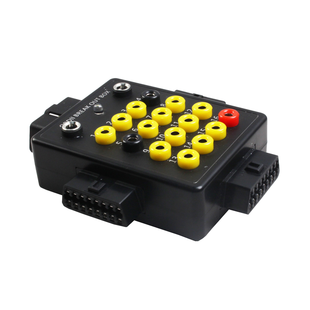
The OBD-II signal conversion box is used for engine-related tests or experiments. Usually, the equipment is connected in series between the ECU and the harness diagnostic seat for the tester to intercept signal measurements or artificially simulate the fault.
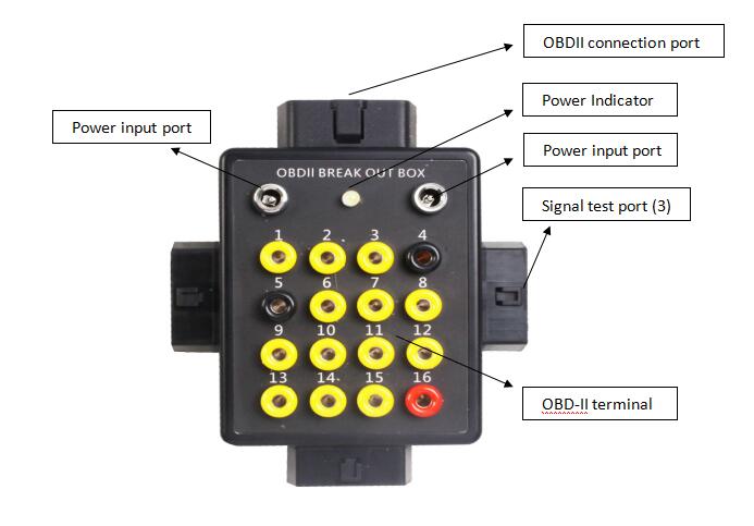
OBD-II Terminal Function Description:
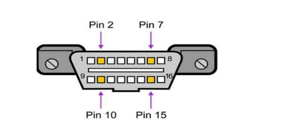
The OBD interface uses a trapezoidal 16-pin connector. Each pin is defined as follows:
1,3,8,9,11,12 and 13 are not assigned and may be defined by the vehicle manufacturer;
2、SAE-J1850 PWM and SAE-1850 VPW bus are positive;
4、Body ground;
5、Signal ground;
6、CAN high(ISO 15765-4 and SAE-J2284);
7、K line of ISO 9141-2 and ISO 14230-4 bus;
10、SAE J1850 bus is negative;
14、CAN low(ISO 15765-4 and SAE-J2284);
15、L line of ISO 9141-2 and ISO 14230-4 bus;
16、Battery voltage.
The OBD-II signal conversion box is used for engine-related tests or experiments. Usually, the equipment is connected in series between the ECU and the harness diagnostic seat for the tester to intercept signal measurements or artificially simulate the fault.
OBD-II Terminal Function Description:
The OBD interface uses a trapezoidal 16-pin connector. Each pin is defined as follows:
1,3,8,9,11,12 and 13 are not assigned and may be defined by the vehicle manufacturer;
2、SAE-J1850 PWM and SAE-1850 VPW bus are positive;
4、Body ground;
5、Signal ground;
6、CAN high(ISO 15765-4 and SAE-J2284);
7、K line of ISO 9141-2 and ISO 14230-4 bus;
10、SAE J1850 bus is negative;
14、CAN low(ISO 15765-4 and SAE-J2284);
15、L line of ISO 9141-2 and ISO 14230-4 bus;
16、Battery voltage.